![[Company Logo Image]](_borders/aec_blue_short.GIF)
![]()
![]()
![]()
![]()
![]()
![]()
![]()
![]()

|
|
|
|
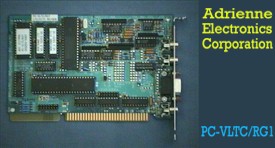
TIME CODE BOARDS FOR IBM PC/XT/AT As you can see from the ordering guide at the end of this page, we offer a wide variety of these boards, ranging from the simplest LTC readers up to our top of the line PC-VLTC/RG1 combination LTC/VITC reader/generator board. We have also designed quite a few variations on these boards, at reasonable costs, for those customers having unique requirements. These ISA bus models are still available and can be shipped from current inventory in most cases except where noted below. We also manufacture newer PCI and USB devices with the same or additional features to these ISA bus models. See our products listing from the home page. Because these boards reside in your computer, you don't have to buy expensive external time code boxes with serial interfaces, plus extra serial ports for your computer. Your program development is easier, and system response is much faster too, since there are no serial data link delays. Typical applications include computerized VTR, ATR, and videodisk monitoring and control, video tape editing, testing of time code equipment and signals, tape logging, and system automation. Options for most boards include a RS232/RS422 serial interface, a SPST relay closure output, and time code checking software. Below you will find information to aid you in selecting the right PC-LTC/VITC/VLTC board to meet your needs. Please call us at 1-800-782-2321, or at the number above, if you have any questions. We look forward to hearing from you. Sincerely, Tracey Ruesch, President P.S. - All boards come with free a DOS "TSR" and Windows NT "service" program which can jam your computer's BIOS and DOS time-of-day clocks to match an incoming LTC/VITC reference signal. Adrienne, AEC, AEC-BOX, PC-207M, PC-LTC, PC-VITC, and PC-VLTC are trademarks of Adrienne Electronics Corporation. SMPTE is a registered trademark of the Society of Motion Picture and Television Engineers, Inc. Windows NT is a trademark of Microsoft Corporation. IBM, IBM PC, IBM PC/XT, and IBM PC/AT are registered trademarks of International Business Machines Corporation. WHAT IS TIME CODE ? Time Code assigns to each video frame (picture) a unique number, having the format Hours:Minutes:Seconds:Frames. This number may then be used for editing and/or control purposes. Time code standards have been around for many years, and are sponsored by both SMPTE (for NTSC) and the EBU (for PAL). Vertical Interval Time Code (VITC) is encoded in the vertical interval (non visible portion) of a video signal. Longitudinal Time Code (LTC) is a specialized audio signal which is usually recorded on a video tape next to its associated video signal, but may also be used in an audio only environment. Use of VITC frees up one audio track for other purposes, such as stereo audio. It also allows time code to be read at very low (including still) tape speeds, where fine positioning is important. However VITC cannot usually be read at tape speeds much above play speed. LTC is commonly used because it is usually lower cost than VITC, can be added to a video tape after the initial video recording, and it can be read during high shuttle speeds (fast forward and rewind). However, due to record/playback limitations of tape machines, LTC cannot be read reliably at very low tape speeds. In many cases LTC and VITC will be used at the same time, because of the advantages each has to offer. BOARD SOFTWARE DESCRIPTION Each PC-LTC/VITC/VLTC board comes with a diskette which contains board test and demonstration software, plus software examples to assist you in your application development. For DOS we provide BASIC, Pascal, C, and 8086 Assembly Language examples. For Microsoft Windows 3.1, Windows 95, and Windows NT, we provide VisualC++, VisualBasic and Assembly Language examples and drivers and/or library. We also have a Borland Delphi program with source code available for your reference. Finally, the board's instruction manual has complete hardware/software interface documentation should you ever need to refer to it. Depending on which board version you have, the test and demonstration software reads and/or generates LTC/VITC time codes under keyboard control, and displays the results on your computer screen. This is especially useful when you are developing your own application software, because then you will know for sure that the board and its LTC, VITC, and/or video sources are operating correctly. Every time your computer is turned on, all PC-LTC/VITC/VLTC boards (except the PC-LTC/IOR board) execute a power-on-self-test (POST). A short message is then displayed on the CRT to let you know that the board is installed correctly and working properly. BOARD HARDWARE DESCRIPTION All PC-LTC/VITC/VLTC boards (except PC-LTC/MMR and IOR) include a coprocessor system, some glue logic, an IBM PC I/O bus interface, plus (as applicable) a video input amplifier, VITC reader and/or generator circuits, and LTC reader and/or generator circuits. In addition, some boards have an optional UART, with buffers for serial communications, and some boards include the optional relay closure output. Because these boards contain a coprocessor, they can operate independently, without slowing down the host computer. A Dual Port RAM (DPRAM) provides the communication link between the coprocessor and the host processor on the system board. These "smart" boards can generate an interrupt whenever a preset time code is reached, when an error occurs, can do data preprocessing, and are easy to customize to your particular application. These boards are memory mapped, which means that your computer can read from and write to the board just like any other memory in the computer. The standard address segments are CC00, CD00, CE00, CF00, DC00, DD00, DE00, and DF00 hex (jumper selectable). Most computers do not use these addresses for anything else. Other addresses are readily available on a custom basis. Up to 64 of these boards can be installed in one computer, provided that you have enough slots for them. To communicate with one of our boards, your software can either poll the board (read memory locations and wait for changes), or you may use interrupts. There are 4 interrupt channels available on the PC and PC/XT, and 8 interrupt channels available on the PC/AT, all jumper selectable. If you have more than one of our boards installed, they may share the same interrupt channel. The PC-LTC/IOR time code reader board differs from all the others in that it uses the I/O address space, and it has no coprocessor. This means that the comparator, relay, serial interface, and other advanced features are not available. It uses I/O addresses 200, 220, 280, 2A0, 300, 320, 380, and 3A0 hex (jumper selectable). This board is all that is needed in many applications, and is very easy to interface to. (Note: The PC-LTC/IOR and MMR models have been discontinued as we can no longer get parts). You will find that our boards are clean, well built, good looking, and reliable. All IC's are mounted in sockets for easy board troubleshooting, repair, and/or customization. COMPUTER REQUIREMENTS All of these boards are designed to work with the IBM PC, XT, AT, and any computers which are 100% compatible, such as the Compaq portable. The IBM PS/2 computers are not supported, except those models which accept the older style plug-in boards. TIME CODE READERS - GENERAL CHARACTERISTICS Our LTC and VITC reader boards can read both SMPTE and EBU format time codes - no hardware changes required. All of the time bits, user bits, AND control bits are available for inspection every time code frame (except IOR boards only read time OR user bits). Standard time code reader features include indicators for tape direction (FWD/REV), drop frame (DF/NDF) status, color frame (CF) status, code format (SMPTE/EBU), and other reader status bits. All of our boards automatically begin reading time code when the power is first turned on. In addition, they may be used as a time code comparator (except IOR boards), and they work with our free "smart key" and "TC_CLOCK" software. VITC READER NOTES Our VITC readers use a proprietary IC to read VITC data from the incoming video signal. It is assumed that the horizontal scanning frequency of the incoming video signal differs from nominal values by no more than +5%. This generally applies for tape speeds from -1x to STILL to +3x. The VITC reader software automatically selects the VITC line numbers to read, or you may specify the line numbers to be used (via your software). The CRC byte is checked every field. The video/VITC input connector is an RCA phono jack. This input is high impedance (bridging) and expects to see a clean 1Vpp video signal. Video signals which have been severely low pass filtered or otherwise distorted will not be readable, due to the short pulses (high frequencies) used to encode the VITC data. LTC READER NOTES The wideband LTC reader uses a proprietary IC to read time code AND user bits simultaneously at speeds from 1/30x to 80x. It reads valid SMPTE and EBU LTC signals in both the forward and reverse directions, with LTC input signal levels ranging from 50mVpp to 20Vpp. The differential LTC input amplifier cancels out common mode noise signals such as "hum". The input connector is an RCA phono jack. PC-VLTC/RDR COMBINATION LTC/VITC READER NOTES This board disables VITC reads above 2x play speed. However, at all other speeds, both the LTC and VITC data will be available concurrently. In addition, to simplify your software, the board can be set to automatically switch back and forth between reading LTC and VITC, depending on tape speed and signal quality. TIME CODE GENERATORS - GENERAL CHARACTERISTICS All time code generator functions are under full software control, including time bits, user bits, control bits (like DF/NDF), frames per second, time code format (SMPTE/EBU), VITC line selection, etc. Time bits are automatically incremented every frame without slowing down the host computer. All bits may be changed every frame if desired. The generator may also be stopped and started under software control. Status outputs include the current time bits, video field identification (no color framing capability), and the status of the sync source (LTC or video), if any. The on-board time code comparator software may be used to monitor the current generator time, if needed. VITC GENERATOR NOTES The VITC generator circuitry uses a proprietary IC to add VITC to the video signal which is currently being looped through the board. Our boards cannot read and write VITC at the same time. The CRC byte and video field ID bit, along with the time bits, are updated automatically every video field. Note that the generator is actually an ADDER, which means that the line on to which VITC is to be added MUST BE BLANK. If a VITC signal has already been recorded on the desired line, you will have to find some other line. Also note that VITC cannot be added to the video signal on an existing video tape - it must be ADDED during original recording or while dubbing to another tape. LTC GENERATOR NOTES The LTC generator can either freerun or use the incoming video signal as a phase and frequency reference. The generator output "coasts" through video dropouts up to one second long. The phase of the LTC output may be determined to within one tenth frame. The PC-LTC/RG1 board includes an LTC reader, which allows it to use the LTC input as a phase and frequency reference for the LTC output. The LTC input data may be transferred automatically to the LTC output data, even if a video signal is used for sync. Other frequency sources, such as film tach, the PC's clock, and digital audio clocks are available on a custom basis. The EBU LTC generator hardware differs slightly from the SMPTE generator hardware in order to change the output rise time from 25us (for SMPTE) to 50us (for EBU). "SMART KEY" SOFTWARE INCLUDED Included on the diskette which comes with all time code reader boards is a program which allows the current time code to be read into your spreadsheet, word processor, or other application program with a single keypress. Thus many of our users don't need to write any software at all! This resident DOS program, once installed, requires less than 1kbyte of memory. TIME CODE COMPARATOR AND OPTIONAL RELAY The standard time time code comparator software can be set to send an interrupt to your computer when a preset time code is reached. This frees up the host computer for other tasks. The optional SPST (normally open) relay can be turned on/off at will, or can be set to close when the comparator finds a match. SERIAL INTERFACE OPTION The serial interface option provides both RS232 and RS422 drivers and receivers. The data rate can be programmed to be from 300 to 38400 baud, and you can set the UART for 7 or 8 data bits and odd/even parity. A typical application for the serial interface is tape machine or videodisk control. The serial interface on these boards is not compatible with, but also does not interfere with, the standard COM1 and COM2 serial ports on your computer. Because the UART is controlled by the on-board coprocessor, the host computer does not get slowed down by I/O routines, buffers, etc. Transmit and receive data buffers are built in to our board software, along with break character and powerful character string transmission routines. OPTIONAL TIME CODE CHECKING SOFTWARE This optional software package (on diskette) can be used for analyzing and checking longitudinal time code signals for discontinuities, bit errors, dropouts, DF/NDF errors, counting errors, invalid BCD codes, and more. Automatically logs everything to disk files for later retrieval or hard copy. Now you can analyze and fix tapes before beginning expensive edit sessions! A PC-LTC/RDR or PC-LTC/RG1 board is required. The PC-LTC/CHK software can scan tapes at up to 10x play speed, both forward and reverse, looking for dropouts and other errors. It also can analyze video-to-LTC phasing with an accuracy of 5us. This checking software does not work with the PC-LTC/IOR board, and you cannot determine video phasing unless you have the PC- LTC/RG1 board (which includes a video sync input). PC-LTC, PC-VITC, AND PC-VLTC ORDERING GUIDE (US$) Model Description Price ================================================================= |
Copyright © 2006
Adrienne Electronics Corporation
|