![[Company Logo Image]](_borders/aec_blue_short.GIF)

![]()
![]()
![]()
![]()
![]()
![]()
![]()
![]()

|
|
|
|
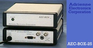
AEC-BOX-25 Literature VITC-TO-LTC TRANSLATOR WITH RS232/RS422 The AEC-BOX-25 was designed to provide a low cost way of translating VITC to LTC. It can also be used as a standalone video synchronized LTC generator, or as an RS232/RS422 serially controlled VITC reader, LTC generator, and/or VITC-to-LTC translator. All of the time, user, and embedded bits can be read and/or set every time code frame. Also, the standard time code comparator software allows the box to interrupt a host computer whenever a predetermined time or user bits pattern is detected. Typical applications for the AEC-BOX-25 include tape dubbing, inserting new user bits while dubbing, tape logging, adapting VITC output devices to LTC-only equipment, and supplying a steady (readable) LTC output while a VITC input signal is "still". If your application requires something a little different from what you see here, please give us a call. These boxes (and their software) have been designed with customization in mind. Since we are a small company, we can (usually) respond quickly to your particular needs, and at a reasonable price. Related products include our PC-LTC, PC-VITC, and PC-VLTC families of internal LTC/VITC reader, generator, and translator boards for IBM PC/XT/AT personal computers (if slots are available), and our AEC-BOX-1/2/10/20 LTC/VITC reader boxes with RS232/RS422 serial interfaces. Below you will find information which describe the AEC-BOX-25 in more detail. Please call us at 1-800- 782-2321, or at the number above, if you have any questions. We look forward to hearing from you. Sincerely, Tracey Ruesch, President Adrienne, AEC, AEC-BOX, PC-207M, PC-LTC, PC-VITC, and PC-VLTC are trademarks of Adrienne Electronics Corporation. SMPTE is a trademark of the Society of Motion Picture and Television Engineers, Inc. IBM, IBM PC, IBM PC/XT, and IBM PC/AT are trademarks of International Business Machines Corporation. WHAT IS TIME CODE ? Time Code assigns to each video frame (picture) a unique number, having the format Hours:Minutes:Seconds:Frames. This number may then be used for editing and/or control purposes. Each time code "frame" actually includes the time bits (just mentioned), 32 "user" bits (for tape ID's, etc.), and 6 more special "embedded" bits, such as the SMPTE drop frame (DF/NDF) flag. Time code standards have been around for many years, and are sponsored by both SMPTE (for NTSC systems) and the EBU (for PAL systems). Vertical Interval Time Code (VITC) is typically present on two nonadjacent lines in the vertical interval (non visible portion) of a video signal. Longitudinal Time Code (LTC) is a specialized audio signal which is usually recorded on a video tape next to its associated video signal, but may also be used in an audio only environment. The use of VITC frees up one audio track for other purposes, such as stereo audio. It also allows time code to be read at very low (including still) tape speeds, where fine positioning is important. However VITC cannot usually be read at tape speeds much above play speed. LTC is commonly used because it is lower cost than VITC, can be added to a video tape after the initial video recording, and it can be read during high shuttle speeds (fast forward and rewind). However, due to record/playback limitations of tape machines, LTC cannot be read reliably at very low tape speeds. In some cases both LTC and VITC are used at the same time, because of the advantages each has to offer. AEC-BOX PHYSICAL DESCRIPTION The AEC-BOX-25 is packaged in a small (modem sized), rugged (all metal), and attractive standalone enclosure. For reliability, and for your convenience, each box has its own internal power supply, for which 115VAC/230VAC is required. Each power supply is Hi-Pot tested for your (and our) safety. NTSC/SMPTE AND PAL/EBU COMPATIBILITY When the power is turned on, the AEC-BOX-25 defaults to either NTSC/SMPTE or PAL/EBU operations (see ordering guide). However, if a video signal is present, the AEC-BOX-25 will automatically detect and adapt to the incoming video standard. No DIP switch, wiring, or EPROM changes are required to accomplish this. Just hook up whatever video signal you want to work with. VITC READER NOTES The video/VITC input connectors are standard BNC's. This is a high impedance looping input, with looping frequency response of +0.1dB maximum from 0 to 5MHz. Input levels of 0.7Vpp to 2.0Vpp are accepted. VITC signals which have been severely low pass filtered or otherwise distorted will not be readable, due to the short pulses (high frequencies) used to encode the VITC data. Our VITC reader uses a proprietary IC to read VITC data from the incoming video signal. It is assumed that the horizontal scanning frequency of the incoming video signal differs from nominal values by no more than +5%. This generally applies for tape speeds from -1x to STILL to +3x. On many machines, VITC can be read at speeds up to +10x (is highly machine dependent). The VITC reader software automatically selects the VITC line numbers to read, or you may specify the line numbers to be used (via your software). The CRC error byte is verified for every VITC line read. LTC GENERATOR NOTES The LTC generator will quickly and automatically lock to the incoming video sync signal. In the event that a video dropout is detected, the LTC generator output will "coast" for as long as needed, then smoothly slide back into alignment when the video sync signal returns. In cases where no video sync input is detected, the LTC generator will freerun with about 0.1% maximum frequency error. When present, the VITC reader data is continuously jammed into the LTC generator data such that the LTC output data will be correctly aligned ("in time") with the VITC input data. The RCA jack "LTC OUT" output is 1Vpp, low impedance (less than 100 ohms), and has sloped rising and falling edges per the SMPTE standard. The LTC output frequency is always "play speed", which makes it easy to read, but will confuse any LTC speed sensors which monitor the bit frequency. The LTC generator repeats or skips frame counts as needed to properly follow the VITC input tape speed. TIME CODE COMPARATOR AND OPTIONAL RELAY The standard time code comparator software can be set to send an ASCII "=" character to your computer whenever a preset time bits (or user bits) pattern is detected. This frees up the host computer for other tasks. Standalone (fixed) use of the comparator is also possible via EPROM modifications. The optional SPST normally open ("form A") relay can be turned on/off at will, or can be set to close whenever the comparator finds a match. The contacts are intended for switching signals, not high voltages or currents. This relay option is usually used for controlling other machines/devices at precise times. For custom applications, a second relay is also available (call). SERIAL INTERFACE CHARACTERISTICS For your convenience, the AEC-BOX-25 has both RS232 and RS422 inputs and outputs. These signals are present on different pins of the 9-pin serial connector. For the RS422 case, the pinout is that of an ESbus Tributary. For the RS232 case, a nonstandard cable is required to interface to 9-pin (PC/AT) and 25-pin (standard) RS232 ports. Via internal DIP switches, baud rates of 1200, 9600, 19200, and 38400 are available. You may also select ODD/EVEN/NONE parity, 7/8 data bits, and the box address (for polled modes). As shipped from the factory, the AEC-BOX-25 is in the BROADCAST mode, which means that a message is automatically transmitted every LTC generator frame. The AEC-BOX-25 can also be placed into the POLLED mode, in which case the box only transmits data when requested to do so. By assigning a different address to each box, several can be controlled (and read) from a single RS422 serial port. In both the polled and broadcast modes, the standard serial interface uses 8 bits per character, which we call the BINARY protocol. Alternatively you may choose to use 7 data bits per character, which changes the box to the ASCII protocol. The ASCII protocol uses standard ASCII characters for all I/O, but is slower and much less powerful than the BINARY protocol. The manual which comes with this product fully describes the BINARY BROADCAST, BINARY POLLED, ASCII BROADCAST, and ASCII POLLED modes of operation. See the next page for a description of the the factory default BINARY BROADCAST mode. BINARY BROADCAST MODE The factory default serial communications setting for the AEC- BOX-25 is BINARY BROADCAST mode, 9600 baud, 8 data bits, ODD parity, and 1 stop bit. For compatibility purposes, this protocol is virtually identical to that of our AEC-BOX-1/2/10/20 time code reader boxes. At the start of every LTC generator frame, the AEC-BOX-25 will transmit the following status message:
AEC-BOX TIME CODE TRANSLATORS ORDERING GUIDE (US$) Model Description Price ================================================================= |
Copyright © 2006
Adrienne Electronics Corporation
|