![[Company Logo Image]](_borders/aec_blue_short.GIF)

![]()
![]()
![]()
![]()
![]()
![]()
![]()
![]()

|
|
|
|
BRIEF: These devices have been designed to provide a low cost way of reading LTC and/or VITC using a variety of personal computers and other devices. This allows the computer/controller to log video tape if the time code source is an analog signal. This is a great feature that allows these unit to work with equipment such as Apple's Final Cut Pro / Final Cut Studio to capture live time code when ingesting live camera or video signals. As of mid 2009, the AEC-BOX-10 and AEC-BOX-20 models are available in limited supply and the AEC-BOX-1 and AEC-BOX-2 are out of production. See our newer model, AEC-uBOX-2 to replace the functionality of the AEC-BOX-1 and AEC-BOX-2 models as well as having CE and RoHS compliance. Contact the factory for specific details. STANDALONE LTC/VITC READERS WITH
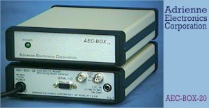
RS232/RS422 The AEC-BOX-1/2/10/20 products were designed to provide a low cost way of reading LTC and/or VITC using a variety of personal computers and other devices. All of the time, user, and embedded bits are available every time code frame. With the exception of the AEC-BOX-1, comparator software is included as a standard feature, which allows the box to interrupt the host computer whenever a preset time or user bits value is detected. Typical applications for these boxes include tape logging, synchronizing the PC's clock with an external time code, and precise automation of various computer controlled systems. Since all of these boxes use the same message protocol, your product can effectively make use of either LTC or VITC, or both, without having to make any radical hardware or software changes. If your application requires something a little different from what you see here, please give us a call. These boxes (and their software) have been designed with customization in mind. Since we are a small company, we can (usually) respond quickly to your particular needs, and at a reasonable price. Related products include our PC-LTC, PC-VITC, and PC-VLTC families of internal LTC/VITC reader and generator boards for IBM PC/XT/AT personal computers (if slots are available). Below you will find information to aid you in selecting the right AEC-BOX-1/2/10/20 time code reader to meet your needs. Please call us at 1-800-782-2321, or at the number above, if you have any questions. We look forward to hearing from you. Now a spcial note: These boxes can also be configured to emulate "Sony Protocol" serially controlled VTRs, allowing direct use with many tape logging programs. This is a great feature that allows these unit to work with equipment such as Apple's Final Cut Pro / Final Cut Studio to capture live time code when ingesting live camera or video signals. (models -2, -10 & -20 only). See more details here. (This link takes you to our new product that is replacing the AEC-BOX-2.) Sincerely, WHAT IS TIME CODE ? Time Code assigns to each video frame (picture) a unique number, having the format Hours:Minutes:Seconds:Frames. This number may then be used for editing and/or control purposes. Each time code "frame" actually includes the time bits (just mentioned), 32 "user" bits (for tape ID's, etc.), and 6 more special "embedded" bits, such as the SMPTE drop frame (DF/NDF) flag. Time code standards have been around for many years, and are sponsored by both SMPTE (for NTSC systems) and the EBU (for PAL systems). Vertical Interval Time Code (VITC) is typically present on two nonadjacent lines in the vertical interval (non visible portion) of a video signal. Longitudinal Time Code (LTC) is a specialized audio signal which is usually recorded on a video tape next to its associated video signal, but may also be used in an audio only environment. The use of VITC frees up one audio track for other purposes, such as stereo audio. It also allows time code to be read at very low (including still) tape speeds, where fine positioning is important. However VITC cannot usually be read at tape speeds much above play speed. LTC is commonly used because it is lower cost than VITC, can be added to a video tape after the initial video recording, and it can be read during high shuttle speeds (fast forward and rewind). However, due to record/playback limitations of tape machines, LTC cannot be read reliably at very low tape speeds. In many cases both LTC and VITC are used at the same time, because of the advantages each has to offer. AEC-BOX PHYSICAL DESCRIPTION AEC-BOX time code readers are packaged in small (modem sized), rugged (all metal), and attractive standalone enclosures. For reliability, and for your convenience, each box has its own internal power supply, for which 115VAC/230VAC is required. Each power supply is Hi-Pot tested for your (and our) safety. SPECIAL NOTES ON AEC-BOX-1 The AEC-BOX-1 is a low cost play speed LTC reader with RS232 and RS422 outputs. Because it is a transmit only device, there are no polled modes of operation, and the comparator is not available. Please keep these limitations in mind throughout the following pages. Despite what we just said, the AEC-BOX-1 does provide the cheapest, simplest, and best solution for many LTC reader applications (such as logging tapes). TIME CODE READERS - GENERAL CHARACTERISTICS All AEC-BOX time code readers automatically read both SMPTE/NTSC and EBU/PAL time code formats - no hardware changes are required. All of the time bits, user bits, AND embedded bits (such as DF/NDF) are available for inspection every time code frame. In addition, status bits indicate the current tape speed, whether any frames have been skipped, and other useful information. LTC READER NOTES The LTC input connector is a standard RCA phono jack. LTC input levels of 100mVpp to 10Vpp are readable. The standard single ended input may be converted to a differential input by removing one shorting jack. In either case, input impedance is at least 10kohms. High quality input amplifiers and processors can recover LTC data properly even from poor quality input signals. A proprietary IC is used to read all LTC bits simultaneously, at speeds up to 80 times play speed, in both the forward and reverse directions. LTC parity is checked automatically. VITC READER NOTES The video/VITC input connectors are standard BNC's. This is a high impedance looping input, with looping frequency response of +0.1dB maximum from 0 to 5MHz. Input levels of 0.7Vpp to 2.0Vpp are accepted. VITC signals which have been severely low pass filtered or otherwise distorted will not be readable, due to the short pulses (high frequencies) used to encode the VITC data. Our VITC readers use a proprietary IC to read VITC data from the incoming video signal. It is assumed that the horizontal scanning frequency of the incoming video signal differs from nominal values by no more than +5%. This generally applies for tape speeds from -1x to STILL to +3x. On many machines, VITC can be read at speeds up to +10x (is highly machine dependent). The VITC reader software automatically selects the VITC line numbers to read, or you may specify the line numbers to be used (via your software). You may also instruct the box whether to read VITC from EBU/PAL or SMPTE/NTSC signals (the power on default is SMPTE/NTSC, unless you request the "EBU" option). The CRC error byte is verified for every VITC line read. AEC-BOX-20 COMBINATION LTC/VITC READER NOTES The AEC-BOX-20 automatically selects the best of the LTC and VITC inputs to be sent to the RS232/RS422 output. If desired, you may control (via software) whether the box should read LTC or VITC at any given time. TIME CODE COMPARATOR AND OPTIONAL RELAY On the AEC-BOX-2, 10, and 20, the time code comparator can be set to send an ASCII "=" character to your computer whenever a preset time bits (or user bits) pattern is detected. This frees up the host computer for other tasks. Standalone (fixed) use of the comparator is possible via EPROM modifications. The optional SPST normally open ("form A") relay can be turned on/off at will, or can be set to close whenever the comparator finds a match. The contacts are intended for switching signals, not high voltages or currents. This relay option is usually used for controlling other machines/devices at precise times. For custom applications, a second relay is also available (call). SERIAL INTERFACE CHARACTERISTICS For your convenience, AEC-BOX time code readers have both RS232 and RS422 inputs and outputs (AEC-BOX-1 has outputs only). These signals are present on different pins of the 9-pin serial connector. For the RS422 case, the pinout is that of an ESbus Tributary. For the RS232 case, a nonstandard cable is required to interface to 9-pin (PC/AT) and 25-pin (standard) RS232 ports. Via internal DIP switches, baud rates of 1200, 9600, 19200, and 38400 are available. Also, you may select ODD/EVEN/NONE parity, 7/8 data bits, and the box address (for polled modes). As shipped from the factory, AEC-BOX time code readers are in the BROADCAST mode, which means that a message is automatically transmitted every time code frame. The AEC-BOX-2, 10, and 20 can also be placed into the POLLED mode, in which case the box only transmits data when requested to do so. By assigning a different address to each box, several can be controlled (and read) from a single RS422 serial port. In both the polled and broadcast modes, the standard serial interface uses 8 bits per character, which we call the BINARY protocol. Alternatively you may choose to use 7 data bits per character, which changes the box to the ASCII protocol. The ASCII protocol uses standard ASCII characters for all I/O, but is slower and much less powerful than the BINARY protocol. The manual which comes with each AEC-BOX time code reader fully describes the BINARY BROADCAST, BINARY POLLED, ASCII BROADCAST, and ASCII POLLED modes of operation. See the next page for a description of the the factory default BINARY BROADCAST mode. BINARY BROADCAST MODE The factory default setting for all AEC-BOX time code readers is BINARY BROADCAST mode, 9600 baud, 8 data bits, ODD parity, and 1 stop bit. This allows you to write software which is independent of the particular box being used. Assuming that either the LTC or VITC input is OK (as applicable), the AEC-BOX-1/2/10/20 will transmit the following message every frame (LTC) or field (VITC):
AEC-BOX LTC/VITC READERS ORDERING GUIDE (US$) Model Description Price ================================================================= |
Copyright © 2006
Adrienne Electronics Corporation
|